极限使用状态和极限承载状态是在工程建设领域普遍采用的基本设计原则,岩土体变形与破坏(或强度)研究也因此始终是岩土工程建设需要特别关心的核心问题。不同于建筑结构,上述设计原则在岩土工程实践中的应用则视工程类型、基本地质条件的不同而存在差异。总体而言,岩土工程更多倾向于采用极限承载状态作为设计原则来保证工程对象的施工期和运行期安全,如边坡工程普遍采用反映岩土体强度条件的安全系数来评价设计方案的合理性。当然,在土体或软岩中的工程建设也不乏需综合考虑极限使用状态来控制岩土体变形水平,以满足工程结构设计对变形的要求,典型如地铁隧洞、以及土石坝等工程类型。
数值分析技术是开展岩土体变形与破坏研究的有效手段之一,特别是连续介质力学方法在近年来已得到极为广泛的应用。不过,岩土体变形与破坏实际是其内部结构调整、破裂等细观非连续行为的宏观表现。上述机制性问题在土石坝填筑过程中表现的尤为典型,填料中的岩块在碾压过程中将经历轴向方位重新排序的复杂过程,在填筑碾压应力较高的情形下,该过程中还可以伴生破裂的产生。因此可描述介质细观结构和破裂行为的非连续介质力学方法对岩土体变形与破坏研究而言显然更具先天优势。目前,岩土工程行业内已积累有大量使用ITASCA非连续介质方法PFC进行相关应用的案例。考虑到非连续介质方法对计算机资源要求较高,近年来同时发展了综合FLAC3D、PFC各自优势的连续介质-非连续介质力学耦合技术,在满足岩土体变形破坏机制研究的同时,保证了更为高效的分析效率。
本文推介由ITASCA德国公司提供的一份演示性耦合分析案例,采用FLAC3D-PFC(分别为7.0、6.0版本)及Wall-Zone耦合方法模拟土体在钢管桩沉桩过程中的变形破坏现象。此处未对技术文档作中文翻译,以充分保留作者分析意图、模型设置等信息,模型代码可通过如下云盘地址下载:
百度云盘:https://pan.baidu.com/s/1jOU7FHS1oMhUq7CLaR5wag
提取码:zt2n
|
Date: |
12-13-2019 |
|
To: |
Jim Hazzard (ITASCA Consulting Group, Inc.) |
|
From: |
Benedikt Stille (ITASCA Consultants GmbH.) |
|
Ref: |
Example of a coupled pile simulation with PFC and FLAC3D |
Problem Statement
This example demonstrates the use of coupled FLAC3D-PFC simulations. The model simulates the application of a pile system, which is often used in geotechnical or civil engineering projects for ground stabilization or foundation setup.
A simple pile with a hollow setup is shown in this example, which is typical used for the foundation setup of offshore wind energy turbines. During the simulation the pile will intrude into the soil ground material which is generated of PFC-particles. In order to improve calculation time, the outside areas of the model consist of FLAC3D-zones. The implemented coupling plugin in FLAC3D / PFC was used to setup and run the simulation. The code works in FLAC3D 7.0 as well as in PFC3D 6.0.
Numerical Model
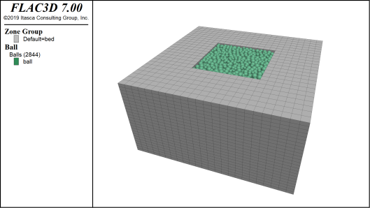
The model is divided in two main parts. The ground material which consists of particles in a “bed” of zones and a pile constructed with zones. In order to create the ground material, a box of zones is created. The box dimensions are free of choice and defined as variables in the code. Inside the box of zones is a free space for particles. The space for particles is also free of choice and defined by variables in the code. For the model installation all zones of the ground material are created initially. Also, the constitutive model and material properties for the zones are set at this point (Table 1). For this example, a simple elastic constitutive model is installed. After installation of zones the free space is filled with particles and the particle contact model is set with the contact assignment table. The ground material is complete (Figure 1) and can be saved as an initial model for pile simulations with different setups.
Table 1: Ground material properties
|
Young modulus [MPa] |
150 |
|
Density [kg/m³] |
2400 |
|
Poisson ratio [-] |
0.25 |

Figure 1: Initial ground material model
Afterwards the pile is installed. Therefore, a function is searching for the actual model top in the particle area to setup the initial position of the pile. The pile is then installed as a hollow cylinder (Figure 2). The length, radius and wall thickness of the pile is free of choice and defined as variables in the code. The constitutive model and material properties for the pile-zones are set at this point. As well as for the ground material a simple elastic model is installed for the pile-zones. The pile material properties were set to simulate a steel material (Table 2). For the intrusion into the ground material, a pre-defined velocity is applied to the pile.
Table 2: Pile material properties
|
Bulk modulus [GPa] |
160 |
|
Shear modulus [GPa] |
80 |
|
Density [kg/m³] |
7850 |

Figure 2: Model after pile installation
Simulation Results
Figure 3 shows the simulation after the pile intrudes the ground material. The most displacements accruing at the pile tip. The boundary between PFC-particles and FLAC3D zones shows a smooth transition of the displacements. The pile velocity is constant.

Figure 3: Displacement in ground material during intrusion of the pile
Listing of Data Files
The example project contains the following input files:
· Example-Pile.dat
· generalFunctions.fis

参考文献:
[1] PFC 6.0 Manual. Itasca Consulting Group, Inc.

